In a pair of Lessons Learned documents published Friday, NERC highlighted an unexpected vulnerability in bulk power system equipment located near shorelines that, coupled with a series of “relay misoperations,” led to a temporary loss of load.
Both reports arose from the same incident, though details about the event — including the location, date, utilities and regional entities involved — were omitted, as is common in NERC’s Lessons Learned reports, which are intended not to shame individual companies but to “provide industry with … information that assists [it] with maintaining the reliability of the bulk power system.”
Storm Leads to Salty Conditions
The incident began with a tropical storm, detailed in the first report. While the storm itself did not directly cause the load loss, it did create the conditions for the problems that developed several days later.
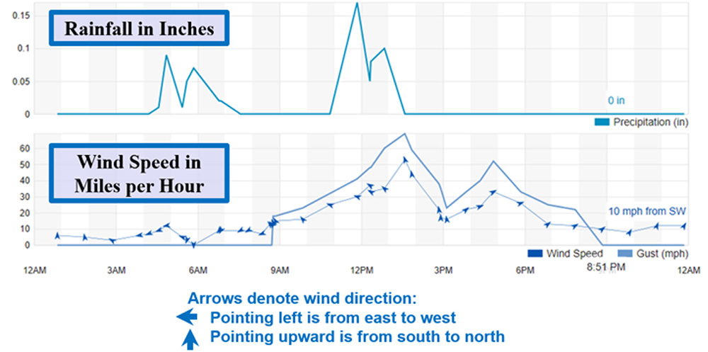
During the storm, the substation experienced high winds (more than 50 mph) and moderate rainfall, about half an inch over several hours, according to a nearby weather station. While the winds dropped off when the rainfall stopped around 1:30 p.m. local time, the wind began to pick up again around 3 p.m. — this time without any rain.
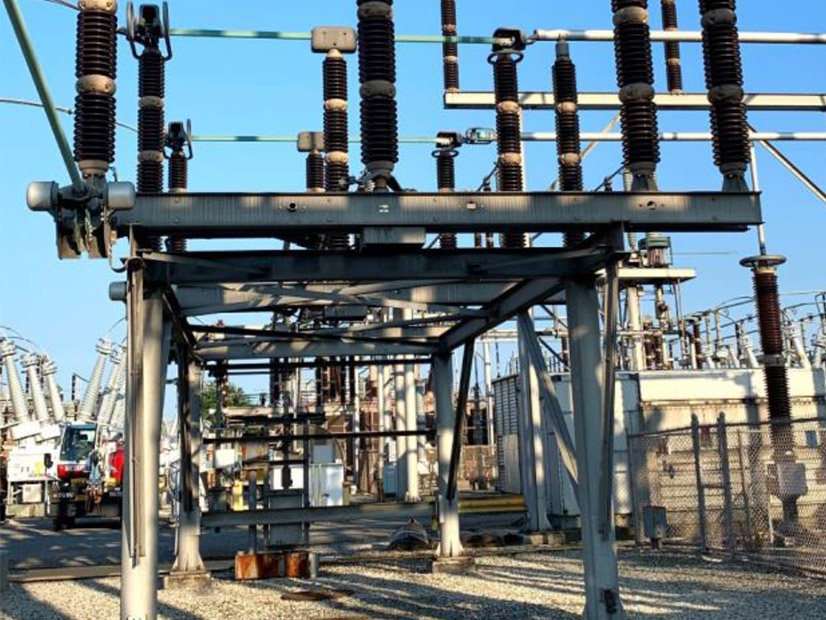
The wind also changed direction, blowing across a saltwater channel and toward the substation. The water in the channel was “churning” and higher than normal for that time of day because of the storm surge. As a result, the wind carried salt spray from the channel to the substation and deposited it on the surfaces of the equipment inside. Because there was no rain to wash it off, a thin, dry film of salt remained on the equipment, including four 345-kV insulator columns.
Because of the lack of rain and low humidity, the salt deposits did not cause any issues the day of the storm. However, they did set the stage for the early morning hours three days later, when a light rain began to fall on the substation. During the initial minutes of rainfall, as the insulators became wet — referred to in the report as the “critical wetting period” — elevated leakage currents began to flow along their surfaces. This led to a temperature rise that began to burn off the salt film, causing uneven voltage gradients that resulted in dry band arcing.
Dry band arcing is not uncommon, but the double-stack construction of the insulator columns meant that several insulators were in close proximity to each other. This created conditions where dry band arcing on one column “had the opportunity to cross over and meet up with the dry band arcing on the adjacent column.” Within 23 seconds, all four insulator columns flashed over, resulting in single-line-to-ground faults.
The faults were cleared quickly, and as the rain continued, the salt washed away, removing the cause of the arcing and allowing normal service to resume. Ordinarily there would not have been any major issues. However, as the second report explains, misoperation of protective relays on other transmission facilities because of the faults caused non-faulted lines connected to the substation to trip, leading to a loss of load that lasted more than 30 minutes.
NERC identified four misoperations in the report:
- A breaker failure relaying scheme incorrectly registered a breaker as closed, and it tripped the adjacent bus section and connected transmission line.
- A backup relaying scheme protecting a phase angle regulator (PAR) did not have a proper polarizing source.
- Saturation of an auxiliary current transformer caused inaccurate input to a line differential relaying circuit, resulting in tripping of the associated transmission line.
- Over-reaching of certain ground distance elements occurred in the stepped distance relaying scheme that serves as backup to the line current differential relaying for two terminals remote from the fault location.
The substation’s operator has addressed each of these issues since the incident. First, the unusual breaker failure scheme, which used current sensing to determine if the breaker has opened in conjunction with a separate timer, will no longer be used; instead, the two functions will be integrated into the same relay. In addition, the PAR protection scheme has been updated to use the proper polarizing source.
The auxiliary transformer that tripped its line has been disconnected, and the system has been modified to “eliminate the need for [it] altogether.” Finally, the ground distance elements that over-reached were put on standby so that they will be armed only when the communications used by the line current differential relaying are unavailable.
Weather, Maintenance Issues Identified
The first report acknowledges the unusual circumstances behind the initial fault — a combination of strong winds, no rain and high seas that led to quick salt deposit — and notes that such phenomena may occur along any salt water coasts worldwide, including inland salt lakes.
“While regular cleaning and maintaining anticontamination coatings may remove and slow contaminant accumulation, awareness of conditions that cause rapid conductive contaminant deposition or remote leakage current monitoring and alarming are important tools for prompting actions that can prevent faults like these,” the report says.
Contributing issues for the relay misoperations include “interconnecting old and new protective relays”; for example, the breaker failure relaying scheme combined a legacy timer with a separate, recently installed current-sensing element, two functions that are normally combined into the same relay. This kind of combination has the potential to “introduce unforeseen problems,” in this case by replacing a normal relay’s internal electronic logic with a mechanical component that could and did fail.
Other vulnerabilities demonstrated by the incident include the possibility of current-sensing elements becoming confused by fluctuated loading levels, as well as excess complexity from adding unnecessary detection and control elements that can lead to misoperation and mechanical damage. Also, the “failure to recognize” the issues presented by lack of polarizing source on the PAR “highlights the need for thorough oversight, peer reviews and simulation testing of protection schemes during the design and commissioning stages of new or upgraded protective relaying installations.”